Contributed article by Maureen Dooley
In the U.S., 519 major airports (1) are presumed contaminated with PFAS (per and polyfluoroalkyl substances), primarily due to the routine use of aqueous film-forming foam (AFFF) for firefighting training. These airport fire training locations present long-term contamination sources that inevitably leach PFAS, contaminants known to be harmful to human health, into the underlying groundwater.
[1]Airports certified under Title 14 Code of Federal Regulation Part 139.
Most PFAS compounds in AFFF are readily transported through the groundwater and threaten to expose communities if water wells or surface water bodies are nearby. This scenario was the case at Martha’s Vineyard Airport (MVY) in Massachusetts, where a PFAS contaminant plume in groundwater was migrating away from a fire training site located at the facility. In response, MVY contracted Tetra Tech, a leading high-end consulting and engineering service provider, to develop a solution for stopping PFAS migration.
CAC Selected as Most Viable Solution at MVY
Currently available options for remediating PFAS in groundwater involve either pumping the groundwater above the surface for treatment (i.e., pump & treat) or filtering in situ (i.e., below the surface) to remove the contaminants. After careful analysis, Tetra Tech determined that remediating PFAS in situ would provide the most cost-effective, efficient, and sustainable option to meet MVY’s objectives.
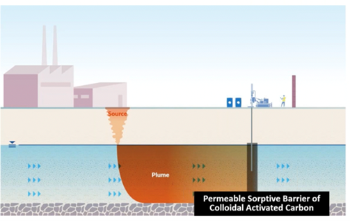
The in situ approach involves injecting colloidal activated carbon (CAC) into the subsurface, which coats the aquifer matrix to create an expansive, in-ground purifying filter that removes PFAS from groundwater and prevents their migrating offsite. (2) The CAC material is applied to the contaminated groundwater through injection boreholes placed in a line to intercept groundwater flow. This permeable sorptive barrier permits water to flow through it while capturing the contaminants onto the carbon-coated matrix (Figure 1 above).
[2] CAC is commercially available as PlumeStop (US Patents #7,585,132; #9,770,743; 9,776,898; 10,005,684; #10,478,876. Europe Patents 3,027,562; #3,105,190).
In situ remediation of PFAS with CAC barriers is a natural filtration method that operates underground to remove PFAS from groundwater. This process does not bring pollutants to the surface, thus avoiding the creation of expensive, management-intensive PFAS waste streams. In contrast, pump & treat would create tons of spent filtration materials, requiring shipping hazardous PFAS waste materials off the island for disposal. With no pumping required, the in situ approach also avoids long-term power consumption, greenhouse gas emissions, and operation and maintenance (O&M) costs, all factoring into the remedy selection at MVY.
“One of the reasons we selected PlumeStop (CAC) was because it didn’t have that ongoing O&M cost. And the fact that we don’t have a disposal cost associated with it is certainly an advantage,” noted Ron Myrick, Vice President at Tetra Tech.
Field-Scale Test Design and Application
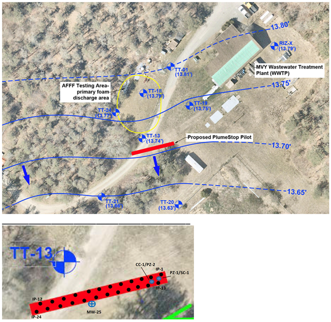
Tetra Tech proposed a field-scale test to assess the CAC technology’s performance in stopping PFAS from migrating out of the AFFF testing area (Figure 2 above). The pilot test plan for installing a CAC barrier was submitted to and approved by the Massachusetts Department of Environmental Protection (MassDEP).
Before installation of the CAC barrier, a contaminant flux measuring device was installed into a monitoring well (FluxTracerTM – patent pending) to delineate the zone containing PFAS contaminants and measure the rate of PFAS moving (i.e., PFAS flux) into the proposed barrier location. According to this analysis, PFAS moved through a more discrete zone than previously estimated. This more precise understanding of the contaminant flux was instrumental in improving the accuracy and placement of the barrier.
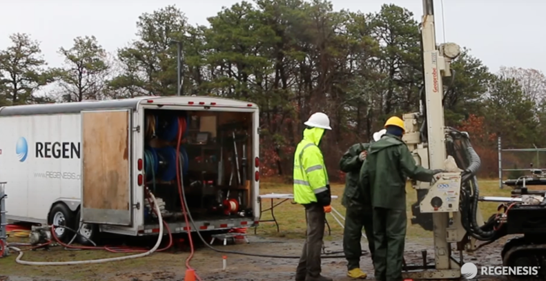
REGENESIS Remediation Services installed the CAC barrier over five days in late 2022, meeting the proposed completion timeline while safely overcoming the cold, wet conditions. The CAC was applied through temporary injection points advanced to the target treatment zone with a hydraulic percussion drilling rig (Figure 3). During the application, PlumeStop’s distribution was confirmed via soil and groundwater sampling in the treatment zone.
Results – CAC Barrier Rapidly Eliminates PFAS
The MassDEP currently regulates six PFAS compounds, referred to as the MassDEP PFAS6, with standard abbreviations: PFOA, PFOS, PFNA, PFHxS, PFHpA, and PFDA.
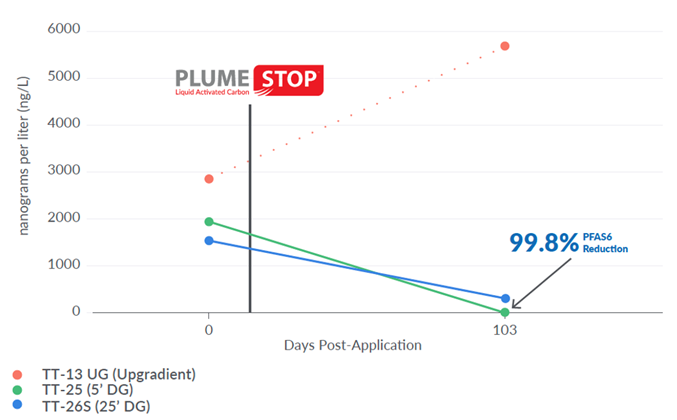
The first performance monitoring sampling event was conducted 103 days post-injection, showing the CAC barrier reducing PFAS6 by 99.8% (Figure 4). Notably, the PFAS concentrations coming into the barrier increased over this timeframe, documented by an upgradient monitoring well.
PFAS were also significantly reduced in wells further away (>25 feet downgradient) from the barrier. This trend should continue as the clean water discharging from the barrier moves downstream.
Conclusion – Colloidal Activated Carbon – a Long-Term, Sustainable, Cost-Effective Solution to Address PFAS Contamination at Airports
The CAC barrier installed at MVY demonstrates the effective elimination of PFAS from groundwater. The early-phase results are typical where this approach has been used to mitigate AFFF releases, including rapid PFAS elimination in the barrier treatment zone and reduced PFAS concentrations further in the plume as the CAC-filtered groundwater continues discharging out of the barrier.
Performance monitoring will continue, with barrier expansion to be considered pending future monitoring results. In the meantime, the current pilot barrier is designed to immobilize PFAS in the plume’s core for 15 years or longer, minimizing plume migration away from the site.
The CAC barrier mitigates the PFAS exposure risk cost-effectively and sustainably. In a recent sustainability assessment conducted by Ramboll at an international airport fire training site, the in situ CAC filtration approach earned a 100% higher sustainability score than currently used pump & treat methods due to its:
• Generating 98% less carbon emissions,
• Reducing the raw material, waste, and energy footprint by 95%, and
• Costing 2.5 to 2.8 times less.
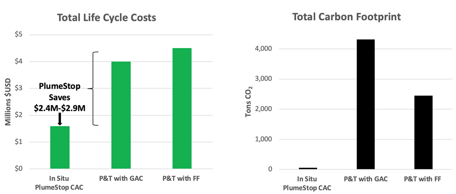
By eliminating mechanical infrastructure, decades of carbon emissions, and transporting hazardous PFAS waste materials off the island, the in situ CAC treatment approach has already proved beneficial for mitigating PFAS at MVY. Its widespread adoption can save billions of dollars in life-cycle costs and eliminate millions of tons of harmful greenhouse gas emissions at aviation facilities and other PFAS-impacted sites worldwide.
About the Author – Maureen Dooley (mdooley@regenesis.com) is the Vice President – Industrial Sector at REGENESIS.